 简体中文
简体中文 English

The manufacturing process of the drive shaft tube
Manufacturing Processes for Transmission Shaft Tubes in Mechanical Applications
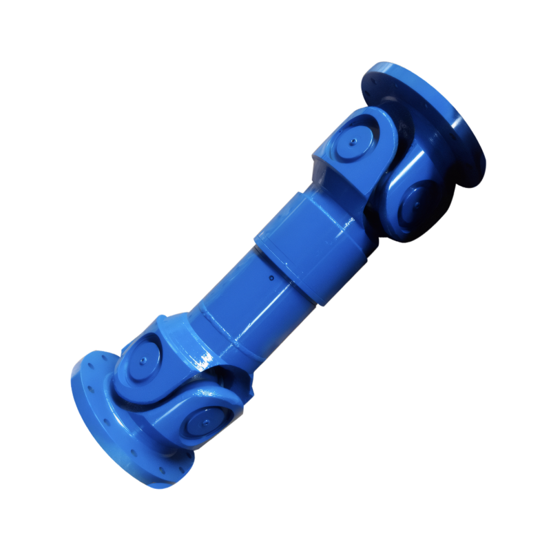
Transmission shaft tubes are critical components in automotive drivetrains and industrial machinery, responsible for transmitting torque between rotating elements while maintaining structural integrity. The manufacturing processes for these tubes require precision engineering to meet stringent performance requirements under dynamic loads and varying environmental conditions.
Cold Drawing with Internal Mandrel for Dimensional Accuracy
Cold drawing using an internal mandrel represents the most advanced technique for producing high-precision transmission shaft tubes. This process begins with selecting seamless steel tubes with diameters and wall thicknesses larger than final dimensions. The tube is then pulled through a die with a fixed internal mandrel, where simultaneous radial and axial forces reduce its diameter while maintaining uniform wall thickness.
Process Parameters and Material Selection
Critical parameters include die angle (typically 24°), mandrel diameter (0.5-1.0mm smaller than final bore), and drawing speed (8-15m/min). For automotive applications, 08Z steel tubes with initial dimensions of φ76mm×2.5mm are commonly processed to φ68.9mm×2.3mm specifications. The cold drawing process induces work hardening, increasing yield strength by 15-20% while maintaining ductility, which is essential for absorbing shock loads in drivetrain systems.
Rotary Swaging for Enhanced Mechanical Properties
Rotary swaging offers an alternative method for shaping transmission shaft tubes, particularly suitable for complex geometries and thin-walled structures. This cold forming process uses rotating dies to apply localized compressive forces, gradually reducing tube diameter through incremental deformation. The technique enables precise control over wall thickness distribution while improving surface finish to Ra 0.8μm or better.
Advantages in High-Volume Production
Compared to traditional extrusion methods, rotary swaging reduces material waste by 30-40% and achieves production rates exceeding 200 tubes per hour. The process also aligns grain flow in the metal structure, enhancing fatigue resistance by up to 50% compared to machined components. In wind turbine yaw drive applications, swaged tubes demonstrate 200,000+ stress cycles without failure under alternating torque loads.
Precision Welding for Structural Integrity
For large-diameter transmission shafts used in mining equipment and marine propulsion, precision welding techniques ensure reliable joint strength between tube segments. Submerged arc welding (SAW) with wire diameter 3.2-4.0mm produces welds with tensile strength exceeding 580MPa, meeting ISO 3183 standards for high-pressure pipelines.
Weld Quality Control Measures
Automated welding systems incorporate real-time monitoring of voltage (28-32V), current (450-550A), and travel speed (0.8-1.2m/min) to maintain consistent bead geometry. Post-weld heat treatment at 620-650°C for 2 hours relieves residual stresses and improves impact toughness to 35J at -20°C. Non-destructive testing using ultrasonic phased array technology detects sub-millimeter defects with 99.8% accuracy, ensuring compliance with API 5L specifications.
Advanced Forming Techniques for Specialized Applications
Hydroforming technology enables the production of complex contour shapes required in electric vehicle drivetrains. High-pressure water (150-200MPa) forces a seamless tube into a die cavity, creating contours with radius-to-thickness ratios exceeding 10:1 without compromising structural integrity. This method reduces part count by 40% compared to assembled components, while improving NVH performance through optimized mass distribution.
Material Behavior Under Hydroforming Conditions
304 stainless steel tubes exhibit 25% higher elongation during hydroforming compared to traditional stamping processes, allowing for tighter bend radii (3× tube diameter vs. 5× for conventional methods). The process also induces beneficial compressive residual stresses (-150 to -200MPa) on the inner surface, increasing fatigue life by 3-5 times under cyclic loading conditions.
 Customized design of drive shafts for special vehicles
 The durability of the drive shaft for off-road vehicles
 Introduction to the structural strength of truck drive shaft
The layout of the drive shaft for a four-wheel drive vehicle
Introduction to the structural strength of truck drive shaft
The layout of the drive shaft for a four-wheel drive vehicle