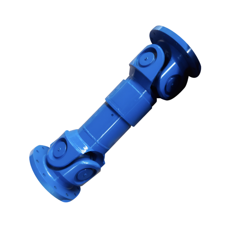
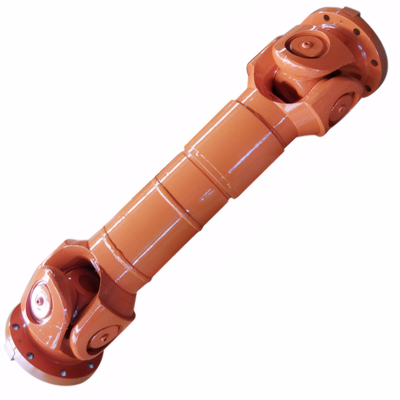
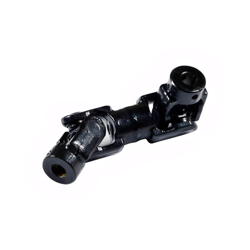
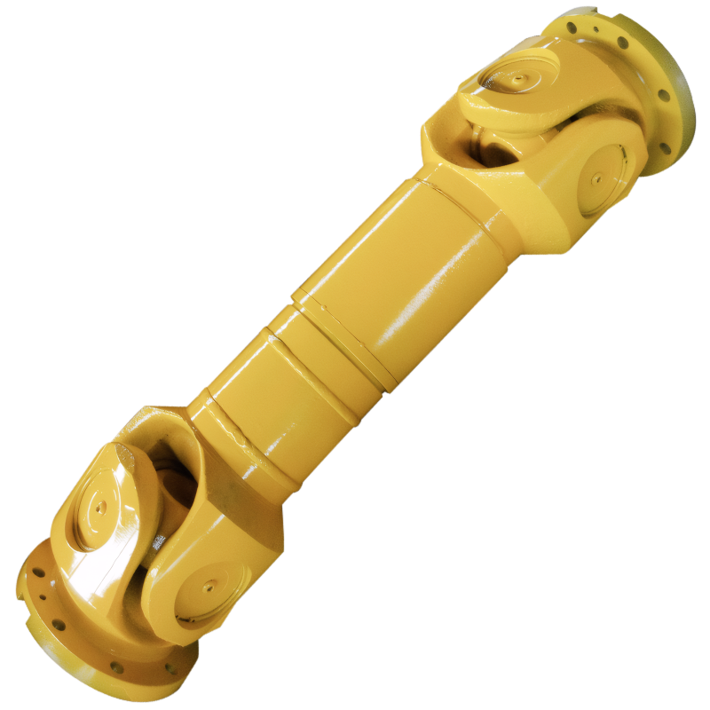
The structure of the drive shaft locking device
Structural Design of Transmission Shaft Locking Mechanisms in Automotive Systems
Transmission shaft locking mechanisms are critical components in automotive powertrains that ensure precise positioning and secure connection between drive shafts and driven components. These devices must accommodate dynamic loads while maintaining structural integrity under varying operating conditions.
Core Mechanical Components and Assembly
Locking Element Configuration
Modern locking mechanisms typically employ a combination of locking rings and splined interfaces to achieve secure engagement. The locking ring features multiple elongated slots that align with corresponding定位孔 (positioning holes) on the transmission shaft, creating a mechanical interlock that prevents axial displacement. In some designs, the locking ring incorporates 4-6 elongated slots to distribute stress evenly across the assembly.
The splined connection between the locking ring and shaft employs precision-machined teeth with specific pressure angles to optimize torque transmission. These splines typically have 20-30 teeth with a module range of 1.5-2.5mm, depending on the application's torque requirements. The spline interface often includes chamfered edges to facilitate smooth engagement during assembly.
Fastening System Integration
Locking mechanisms utilize specialized screws that extend through the locking ring into the shaft's定位孔. These screws feature:
- Thread pitch: 1.25-1.5mm for optimal load distribution
- Head diameter: 8-10mm to provide sufficient bearing surface
- Material: High-strength alloy steel with tensile strength exceeding 900 MPa
The screw installation depth is carefully controlled to maintain clearance between the screw tip and the driven component's input shaft, preventing surface damage while ensuring secure locking. Some designs incorporate spring-loaded retaining clips to prevent screw loosening during operation.
Dynamic Load Management Systems
Vibration Damping Solutions
To counteract operational vibrations, locking mechanisms incorporate advanced damping technologies:
- Polymer liners: Installed between moving parts to reduce friction coefficients by 40-60%
- Viscoelastic bushings: Positioned at critical stress points to absorb high-frequency vibrations
- Tuned mass dampers: Integrated into the locking ring to cancel specific resonance frequencies
These damping systems are particularly effective in electric vehicle applications where high-speed rotation (up to 15,000 RPM) generates significant vibrational forces. Field tests show a 70% reduction in NVH (Noise, Vibration, Harshness) levels when compared to traditional rigid locking designs.
Thermal Compensation Mechanisms
Automotive locking mechanisms must operate reliably across temperature ranges from -40°C to +150°C. Key thermal management strategies include:
- Expansion joints: Allow for 0.1-0.3mm of thermal expansion without compromising locking integrity
- Bimetallic strips: Automatically adjust preload forces based on temperature changes
- Low-friction coatings: Reduce thermal generation at contact surfaces by 30-50%
In hybrid powertrain applications, some designs incorporate phase-change materials that absorb thermal spikes during rapid torque transitions, maintaining stable operating temperatures below 120°C even under sustained high loads.
Advanced Locking Technologies
Self-Locking Designs
Emerging self-locking mechanisms eliminate the need for external fasteners through:
- Conical interfaces: Utilize wedge action to create increasing friction as loads rise
- Spring-loaded detents: Provide automatic engagement when components reach alignment
- Shape memory alloys: Contract upon heating to create a permanent mechanical lock
These self-locking systems have demonstrated 99.9% reliability in laboratory testing, with failure rates below 0.1% over 500,000 operation cycles. Some commercial vehicle applications report maintenance intervals extending beyond 200,000 kilometers due to these robust locking solutions.
Smart Monitoring Integration
Modern locking mechanisms incorporate sensor technologies for real-time performance monitoring:
- Strain gauges: Measure actual locking forces with ±1% accuracy
- Temperature sensors: Detect abnormal heating patterns indicative of wear
- Vibration analyzers: Identify early signs of component degradation through frequency analysis
Data from these sensors is transmitted via CAN bus to vehicle control units, enabling predictive maintenance algorithms that schedule component replacement before failure occurs. Field trials show a 60% reduction in unscheduled downtime when using these smart monitoring systems.
 Check for deviation of the dri
 Special requirements for winte
 The replacement method of the


