

Analysis of the Basic Structure of automotive drive shafts
Understanding the Fundamental Structure of Automotive Driveshafts
Automotive driveshafts serve as the mechanical backbone connecting the engine's power to the wheels, enabling vehicle motion. Their design must accommodate dynamic changes in vehicle geometry while maintaining efficient power transmission. This analysis delves into the core components, operational principles, and structural variations of driveshafts.
Core Components and Their Functions
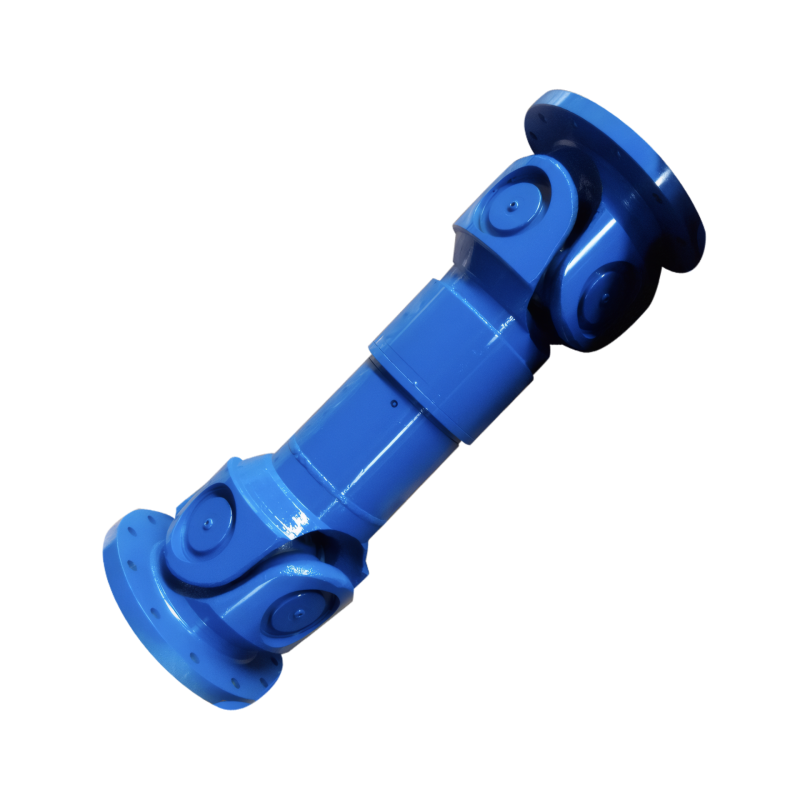
1. Drive Shaft Tube
The primary structural element, typically forged from high-strength alloy steel, forms the driveshaft's cylindrical body. Its lightweight yet rigid construction minimizes rotational inertia while resisting torsional stress. In modern designs, hollow tubes are preferred over solid ones to reduce weight without compromising strength. For example, some heavy-duty trucks employ multi-section tubes connected via flanges to handle extreme torque loads.
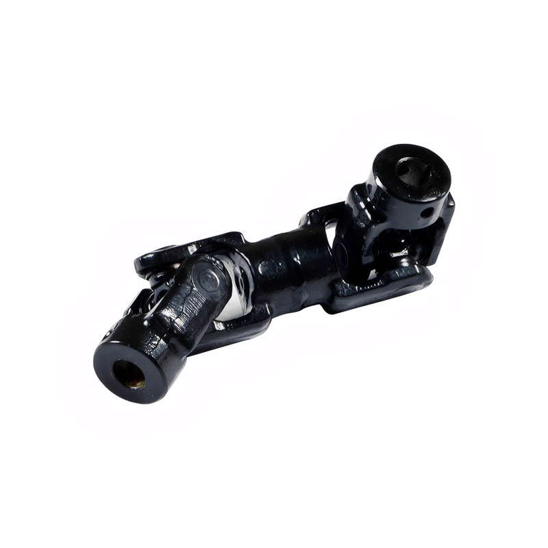
2. Slip Yoke Assembly
This telescoping mechanism compensates for vertical suspension movement. Comprising a splined shaft and mating housing, it allows 50-150mm of axial travel. Advanced models incorporate self-lubricating polymer liners between splines to reduce wear, while sealed designs prevent contaminant ingress. A critical innovation is the integration of vibration dampers within the slip yoke to mitigate noise during rapid length changes.
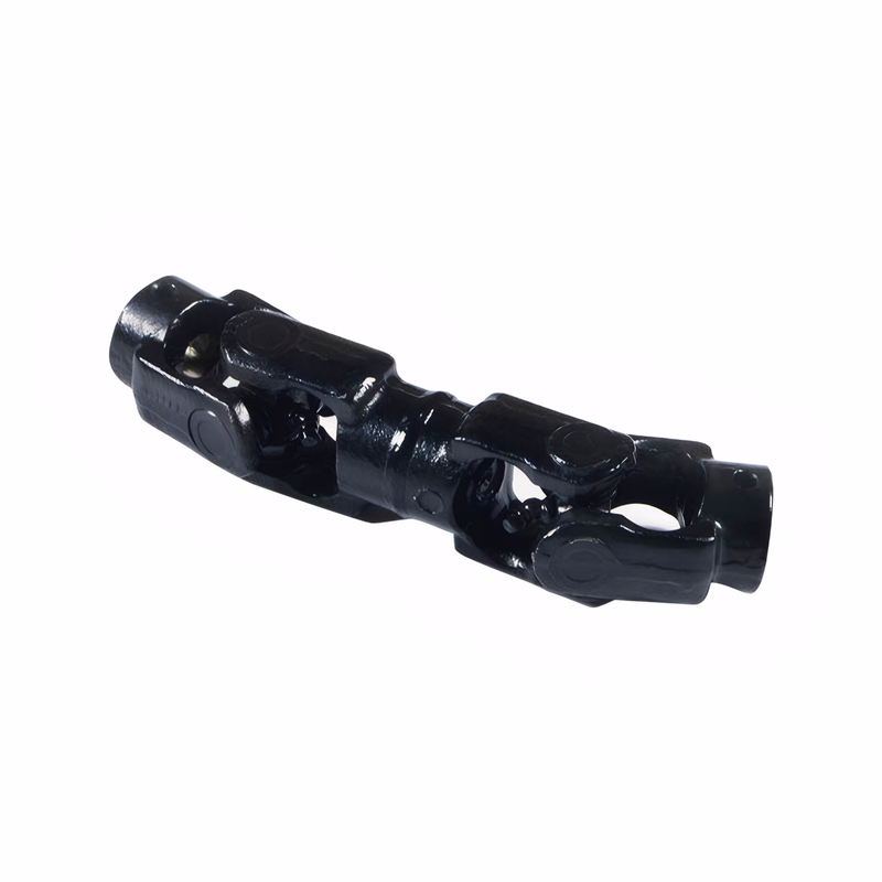
3. Universal Joints (U-Joints)
These cross-shaped couplings transmit torque between misaligned shafts. Modern U-joints feature:
- Needle Bearings: Reducing friction compared to traditional bushings
- Grease Fittings: Enabling periodic lubrication to extend service life
- Cross Trunnion Design: Optimized to maintain near-constant velocity when properly phased
In four-wheel-drive systems, constant-velocity joints (CVJs) replace U-joints at the wheel ends to eliminate speed fluctuations during steering.
Dynamic Adaptation Mechanisms
Angle Compensation Technology
When the driveshaft operates at non-zero angles, geometric variations cause speed fluctuations. Dual-cardan joints (compound U-joints) mitigate this by using two U-joints with phased yokes. For instance, in pickup trucks with rear leaf springs, the driveshaft may operate at 3-6° angles, requiring precise joint alignment to prevent vibrations.
Length Adjustment Systems
The slip yoke's splined interface dynamically alters effective length as the suspension compresses. Some designs incorporate a secondary telescoping section near the differential for additional adjustment range. This is particularly crucial in vehicles with independent rear suspension, where wheel travel can exceed 200mm.
Vibration Isolation Strategies
Modern driveshafts integrate multiple damping solutions:
- Rubber Mounts: At intermediate supports to absorb high-frequency vibrations
- Balancing Weights: Applied during manufacturing to counteract rotational imbalances
- Torsional Dampers: In some CVJ designs to reduce gear rattle during engine load changes
These measures collectively ensure NVH (Noise, Vibration, Harshness) levels remain within acceptable limits.
Structural Variations Across Vehicle Types
Passenger Car Designs
Front-wheel-drive vehicles typically eliminate the traditional driveshaft, using half-shafts with CVJs instead. Rear-wheel-drive sedans employ single-piece tubular driveshafts with one or two U-joints, depending on suspension design. Performance models may use carbon fiber tubes to reduce rotational mass by up to 40% compared to steel.
Commercial Vehicle Configurations
Heavy trucks often utilize multi-piece driveshafts with:
- Intermediate Bearings: Supporting long spans between transmission and differential
- Flange Connections: Allowing modular assembly for different wheelbase configurations
- High-Angle U-Joints: Accommodating extreme articulation in off-road applications
Some articulated buses feature driveshafts with universal joints at both ends and sliding splines in the middle to handle frame flexing.
Specialized Applications
Military vehicles may incorporate:
- Segmented Designs: For quick replacement in the field
- Locking Differentials: Requiring reinforced driveshafts to handle sudden torque spikes
- Corrosion-Resistant Coatings: For extended service in harsh environments
Electric vehicles with in-wheel motors eliminate driveshafts entirely, while hybrid systems may retain shortened versions for range-extender engines.
Maintenance Considerations
Proper driveshaft function requires:
- Periodic Inspection: Checking for worn U-joint bearings or damaged slip yoke splines
- Lubrication Schedule: Following manufacturer recommendations for grease intervals
- Alignment Verification: Ensuring phasing marks on dual U-joints remain aligned during reinstallation
- Balance Checks: After repairs or component replacement to prevent vibrations
Neglecting these aspects can lead to premature failure, manifesting as clunking noises during acceleration or violent vibrations at specific speeds.
 The structure of the middle su
 The connection method of the d
 The function of the splined sh
Check for deviation of the dri
The function of the splined sh
Check for deviation of the dri