

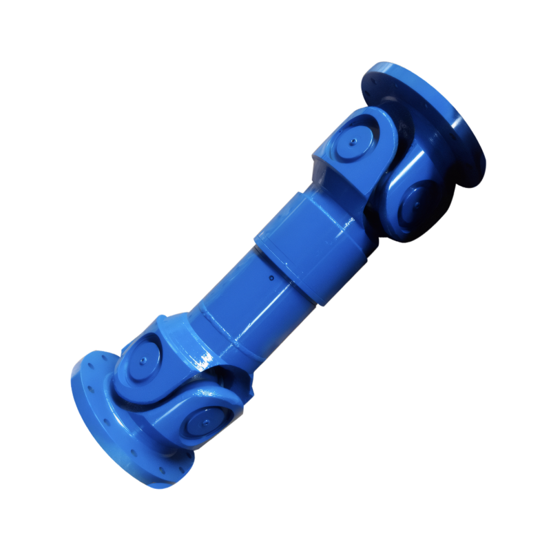
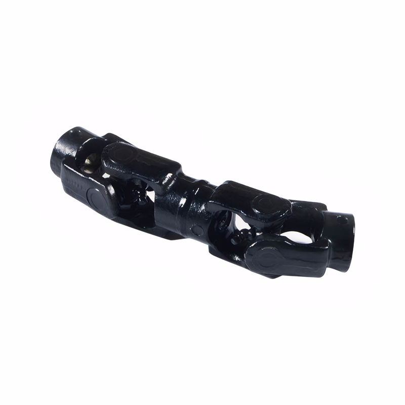
The connection method of the drive shaft flange
Connection Methods of Transmission Shaft Flanges in Mechanical Systems
Transmission shaft flanges serve as critical connection points in mechanical systems, enabling torque transfer between rotating components while maintaining alignment and reducing vibration. These components are widely used in automotive drivetrains, industrial machinery, and aerospace applications, where precise power transmission and durability are essential. Understanding the various connection methods helps engineers select the optimal design for specific operational requirements.
Bolted Connection with Keyways
The most traditional method involves machining keyways on both the transmission shaft and the flange inner bore. A rectangular key is inserted into the aligned keyways, preventing relative rotation between the components. This approach ensures synchronous torque transmission by distributing load across the key’s contact surfaces. However, precise machining tolerances are required to avoid stress concentrations that could lead to premature bearing wear or shaft deformation. In automotive applications, this method is commonly used for connecting driveshafts to differential gears, where high torque loads necessitate robust mechanical interlocking.
Installation Considerations for Keyway Connections
Proper alignment during assembly is critical to prevent uneven load distribution. Engineers must verify that keyway dimensions match the key specifications, with typical clearances maintained between 0.1–0.3mm. Over-tightening bolts can deform the flange, while insufficient clamping force may allow axial movement. Regular inspections should check for keyway wear patterns, as excessive play indicates the need for component replacement. This method is particularly suitable for medium-to-high torque applications where occasional disassembly for maintenance is acceptable.
Threaded Connection Systems
For applications requiring simpler assembly, threaded connections offer an alternative to keyway designs. This method involves machining internal threads on the flange and external threads on the shaft end. A threaded collar or nut is then tightened to secure the connection, eliminating the need for separate keys. The load-bearing capacity depends on thread engagement length and material strength, with typical designs achieving 70–80% of the shaft’s ultimate tensile strength.
Advantages and Limitations of Threaded Connections
Threaded systems reduce part count and simplify installation, making them ideal for mass-produced components like electric motor couplings. However, they are less suitable for high-vibration environments, as thread loosening can occur under cyclic loading. To mitigate this, engineers often incorporate self-locking nuts or thread-locking compounds. In agricultural machinery, where frequent field repairs are needed, threaded connections enable quick component replacement without specialized tools.
Flexible Coupling Integration
Modern drivetrain designs frequently incorporate flexible couplings between transmission shafts and flanges to isolate vibrations and compensate for misalignment. These couplings typically consist of a rubber or polyurethane element with metal inserts that bolt to both components. The elastic material absorbs shock loads from road irregularities in automotive applications, protecting connected gears and bearings from damage.
Performance Characteristics of Flexible Couplings
Material selection significantly impacts coupling lifespan. Fabric-reinforced rubber compounds withstand higher temperatures and chemical exposure compared to standard elastomers, making them suitable for industrial machinery operating in harsh environments. Engineers must balance flexibility with torsional stiffness—excessive compliance can reduce power transmission efficiency, while insufficient give may fail to protect components. In wind turbine yaw drives, multi-layer composite couplings demonstrate 20–30% longer service life than single-material designs by distributing stress more evenly.
Bolted Flange-to-Flange Connections
For large-diameter transmission systems, such as those in marine propulsion or mining equipment, bolted flange-to-flange connections provide a scalable solution. This method uses multiple high-strength bolts arranged in a circular pattern to clamp two flanges together. Gaskets or O-rings placed between mating surfaces create a pressure-tight seal, preventing lubricant leakage or contaminant ingress.
Design Factors for Bolted Flanges
Bolt preload calculation must account for operational loads and thermal expansion. Finite element analysis (FEA) helps optimize bolt spacing to minimize bending moments on the flange. In offshore drilling applications, where saltwater corrosion is a concern, duplex stainless steel bolts with Teflon-coated washers extend maintenance intervals by reducing galling risk. Regular torque audits using ultrasonic measurement tools ensure consistent clamping force throughout the component’s service life.
 The structure of the middle su
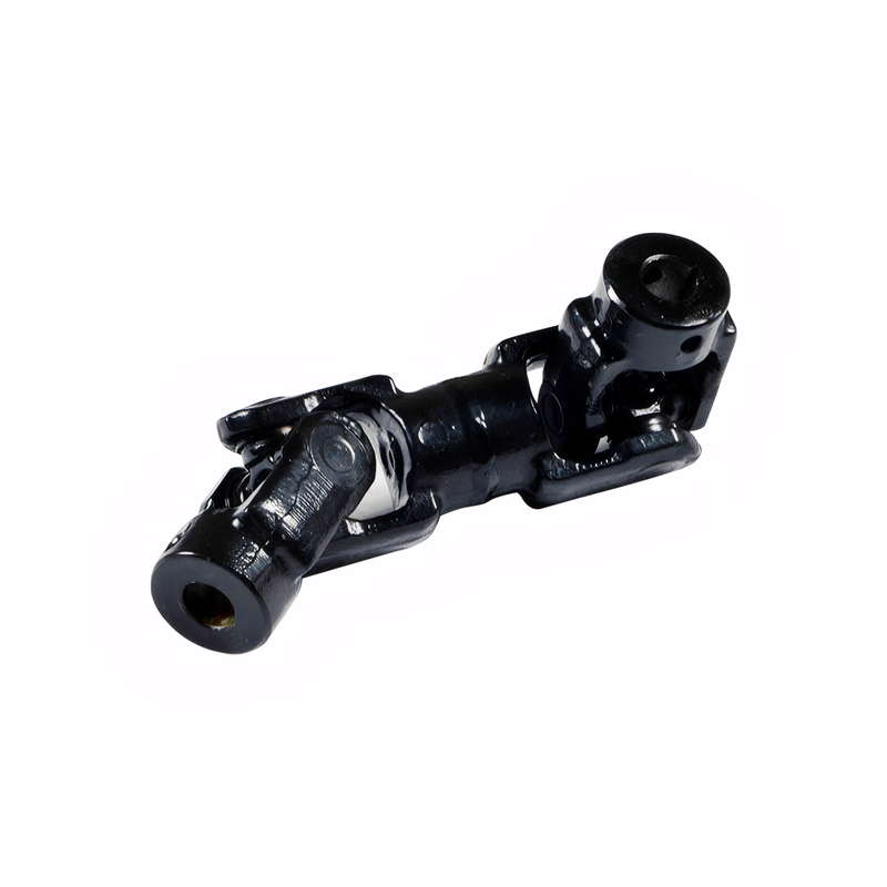 The connection method of the d
 The function of the splined sh
Check for deviation of the dri
The function of the splined sh
Check for deviation of the dri