

Rear-mounted rear-wheel drive type drive shaft structure
Transmission Shaft Architecture in Rear-Engine Rear-Wheel-Drive Vehicles
Rear-engine rear-wheel-drive (RR) vehicles represent a specialized automotive layout where the powertrain is positioned at the vehicle's rear, requiring unique transmission shaft designs to accommodate extended power delivery paths and dynamic operating conditions. This configuration, prevalent in high-performance sports cars and commercial vehicles, demands engineering solutions that balance mechanical efficiency, vibration control, and packaging constraints.
Multi-Section Shaft Assembly for Extended Lengths
Modular Construction with Intermediate Bearings
RR vehicles with wheelbases exceeding 3.5 meters typically employ three-piece transmission shaft systems. These assemblies consist of two intermediate shafts supported by rubber-mounted central bearings and a main output shaft. The central bearing, positioned at 40-60% of the total wheelbase length, reduces critical shaft speeds by 15-20% compared to single-piece designs, preventing resonance frequencies within normal operating ranges. Each shaft section connects via precision-machined spline couplings with 8-12 teeth, allowing 15-25mm of axial movement to compensate for suspension travel.
The central bearing incorporates a pre-loaded tapered roller assembly maintaining 0.02-0.05mm radial clearance, minimizing noise while accommodating 2-3 degrees of angular misalignment. This design enables torque transmission capacities exceeding 4,000 N·m in heavy-duty applications, with some systems incorporating dual rubber mounts to handle 2-3 times the radial loads of passenger vehicles.
Dual Intermediate Shaft Configurations
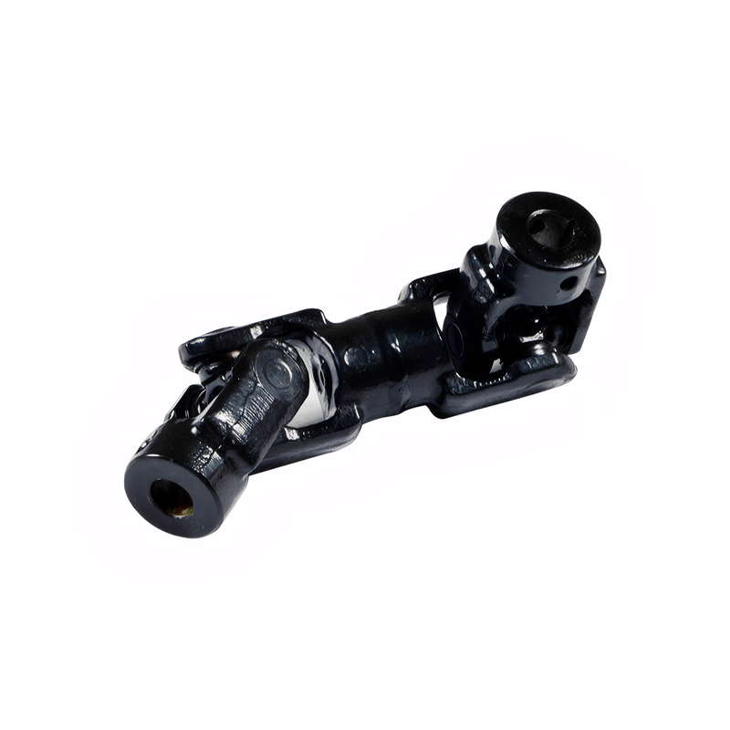
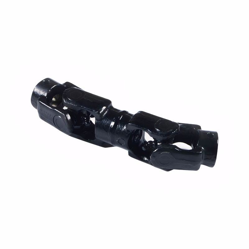
Advanced RR layouts in SUVs and commercial vehicles adopt dual intermediate shafts with four universal joints. This arrangement places two shorter shafts between the transmission and final drive, each supported by independent rubber mounts. The reduced shaft lengths increase critical speeds by 25-30% compared to traditional two-piece designs, while additional universal joints minimize operating angles at each connection point.
Engineering simulations demonstrate this configuration lowers NVH levels by 3-5 dB at highway speeds compared to conventional layouts. The dual intermediate design also improves serviceability, allowing individual shaft replacement without disturbing adjacent components. Some heavy-duty applications incorporate telescopic shaft sections with 100-150mm of axial adjustment to accommodate body flex under load.
Universal Joint Angle Optimization Strategies
Constant Velocity Joint Integration
RR vehicles increasingly incorporate constant velocity (CV) joints at one or both ends of the transmission shaft. These joints maintain equal rotational speeds between input and output shafts across angles up to 47 degrees, eliminating speed fluctuations that cause vibration in conventional universal joint designs. In rear-wheel-drive sedans, CV joints are typically used at the differential end to accommodate suspension travel during acceleration and braking.
For all-wheel-drive systems, CV joints may be present at both transmission and differential connections to handle complex angular relationships between front and rear axles. This arrangement enables smoother power delivery during cornering, with some systems maintaining angular compensation capabilities up to 6 degrees for off-road applications.
Angular Compensation Through Structural Design
Extended wheelbase RR vehicles employ several strategies to maintain proper universal joint angles:
- Transmission/differential positioning: Raising the differential 50-100mm relative to the transmission output reduces vertical angle components
- Shaft pre-bending: Introducing 0.5-1.5 degrees of static pre-bend counteracts deflection under load
- Variable-rate central bearings: Progressive spring rates in rubber mounts maintain alignment across varying load conditions
These measures help keep operating angles below 3 degrees for most driving conditions, minimizing second-order vibrations that become noticeable above 4 degrees. Some high-performance applications incorporate active stabilization systems that adjust suspension geometry in real-time to optimize drive shaft angles.
Material Innovation and Manufacturing Precision
High-Strength Composite Shafts
To reduce weight without compromising strength, manufacturers are experimenting with carbon fiber-reinforced polymer (CFRP) transmission shafts. These components offer 40-60% weight savings compared to steel while maintaining comparable torsional stiffness. CFRP shafts also exhibit better fatigue resistance, with endurance limits 20-30% higher than steel under cyclic loading.
The manufacturing process involves filament winding around precision mandrels, creating hollow tubular structures with optimized fiber orientation. This technique allows for variable wall thicknesses, with thicker sections at universal joint mounting points and thinner sections in central spans. Some designs incorporate metallic end fittings for improved connection reliability with traditional drivetrain components.
Precision Machining Techniques
RR transmission shafts require extremely tight manufacturing tolerances to ensure proper universal joint alignment. Modern production facilities employ:
- CNC spline rolling for consistent tooth profiles with ±0.02mm accuracy
- Laser welding for universal joint assemblies, reducing heat-affected zones by 70% compared to traditional MIG welding
- Cryogenic treatment of steel components, improving wear resistance by 15-20% through microstructure refinement
These processes enable the production of shafts capable of maintaining 0.05mm or better concentricity over their entire 1,500-2,500mm lengths. Some manufacturers incorporate embedded sensors to monitor shaft stress and temperature in real-time, enabling predictive maintenance strategies for fleet operators.
Application-Specific Design Variations
Commercial Vehicle Solutions
Long-wheelbase trucks and buses require specialized RR transmission shaft layouts to accommodate heavy payloads and frequent stop-start operation. These vehicles typically use heavy-duty central bearings with dual rubber mounts to handle 2-3 times the radial loads of passenger vehicles. Splined couplings with larger tooth counts distribute torque more evenly, while grease-filled universal joints extend service intervals to 150,000-200,000 km.
Some heavy-duty applications incorporate telescopic shaft sections that allow for 100-150mm of axial adjustment to accommodate body flex under load. This feature is particularly valuable for articulated buses and commercial vehicles with independent front suspension systems, where relative movement between chassis components can reach 200-300mm.
Off-Road Vehicle Adaptations
RR SUVs designed for off-road use employ transmission shaft layouts with higher operating angle capabilities and reinforced components. These vehicles feature universal joints rated for 6 degrees of continuous operation and 8 degrees of intermittent operation, compared to 3-4 degrees for standard road vehicles. Reinforced central bearings with metal shields protect against debris, while quick-disconnect couplings at intermediate points simplify service in remote locations.
Some off-road designs incorporate slip yokes with extended travel (up to 200mm) for vehicles with independent front suspension systems. This allows for proper drivetrain alignment during extreme articulation events, maintaining power delivery even when individual wheels experience 300-400mm of vertical travel relative to the chassis.
 The replacement method of the
 Key points for maintaining uni
 Detection of unbalanced drive
 Rear-mounted rear-wheel drive